|
|
|
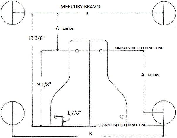
HOW TO MEASURE FOR ORDERING CUSTOM HEADERSHOW TO MEASURE FOR 350 AND 454 CHEVY BRAVO HEADERS It is assumed that the exhaust tips are mounted on the same plane as the gimbal housing and that no set back box or transmission is used. If this is not the case, use the generic drawing below to measure boat. The Mercury Bravo drawing below is viewed from inside the boat and at the transom. All dimensions are from centerline and are based on the exhaust tips being on the same plane as the gimbal housing. Measurements can be given from either gimbal stud or crankshaft reference line, which ever is easier. Always verify that the exhaust tips are equal distance from centerline.
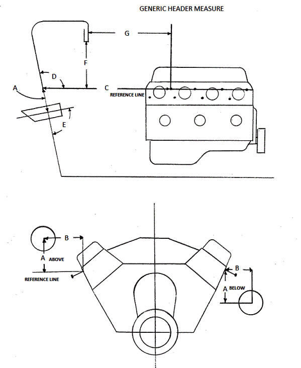
Stock Mercury dimensions are "A" 4 1/4 above gimbal stud reference line and 27 1/4 exhaust tip to exhaust tip. Note: In some cases, there is a interference with the header and the rear deck of the boat and dimensions "F" and "G" from the Generic drawing below must be given.
SCROLL DOWN
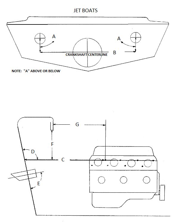
HOW TO MEASURE FOR JET BOAT HEADERS To measure Jet Boat Headers the pump bowl centerline is used as the reference point. It is assumed that the exhaust tips are on the same plane as the pump bowl and that they are of equal distanced from the pump bowl centerline. It is also assumed that a standard 4 degree intake is used and that the driveshaft runs straight, thus the pump bowl centerline is the same as the crankshaft centerline. If this is not the case, use the generic drawing
SCROLL DOWN
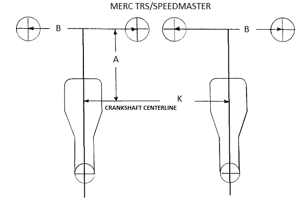
HOW MEASURE FOR MERC TRS/SPEEDMASTER HEADERS To measure for Merc TRS and Speed master Headers the crankshaft centerline is used as the reference point. It is assumed that the exhaust tips are on the same plane as the gimbal housing. In many twin engine applications the outboard tips are canted in and down to allow for deck inference. If this is the case supply A and B dimensions for each exhaust tip. If a not standard transmission is used, refer to the Generic Drawing below. Note: In some cases there is a interference with the header and the rear deck of the boat and dimensions "F" and "G" from the Generic drawing below must be given.
SCROLL DOWN
HOW TO MEASURE FOR HEADERS GENERIC This is the most accurate way to measure for headers. With today's after market engines and parts it's common to have special deck heights on blocks, special exhaust port locations on heads, and non standard engine mount locations in boats. So by using the Header mount location as a reference point it minimizes chance for error. For big block Chevy, install 2" long bolts only in upper exhaust flange holes. For small block Chevy and Ford install 2" longs bolts in exhaust flange holes. Using approximately 1" angle iron as a straight edge place it on top of bolts and flush to port surface. Extend angle aft until it touches transom and is still supported by at least 3 bolts. Mark the outside corner at the transom both vertically and horizontally. Do the same on the other side. Using a level extend a horizontal line past existing exhaust ports. Using a square extend a vertical line past the exhaust tips. These are now reference points for all dimensions.
|
|
|


